What exactly is robot summer?
Robot summer is a nickname for the summer course ENPH253 — Introduction to Instrument Design. The course is exclusive to Engineering Physics students and, as the nickname would imply, is taken over (both) summer terms. Over a period of 6 weeks, students divide themselves amongst 16 groups of 4 to build a fully autonomous robot capable of completing some tasks in a competition. It was a very fun, intense and gratifying experience.
The competition
For my year, the competition involved following black tape across the following multi-terrain track:

The sections in blue are ramps, Rainbow Road is pretty aggressively arched. Each lap across the track was worth 3 points, and there were blocks scattered around that we could pick up, each worth 1 point. This was the first time this competition allowed robots to run simultaneously on the same track, which added some interesting and challenging considerations. If the robot somehow can’t keep going, you may restart it, forfeiting all your lap points, or call it day and keep the current tally.
Our design
We came into this competition with the goal of winning, so we really tried to figure out an “optimal” strategy. We realized we should focus on the basics, speed and consistency (i.e. doing laps without restarting). This immediately removed a few strategies that may have seemed really good for saving time:
- We would not take the IR shortcut: we realized it would be pretty hard to go fast across the rocks and track the IR reliably;
- We would also not take the zipline for the same reasons.
These both turned out to be really good insights. More details on the design:
Chassis and mechanical design
I’ll go into more detail on the chassis development later hopefully. My contributions here came quite late into the course as the robot systems got more integrated.
Electrical design
This was my main role during the first half of the course. I learned a lot about interfacing different circuits here, so I’d like to briefly document my journey through this process. Below is the initial high-level overview I proposed for the robot:
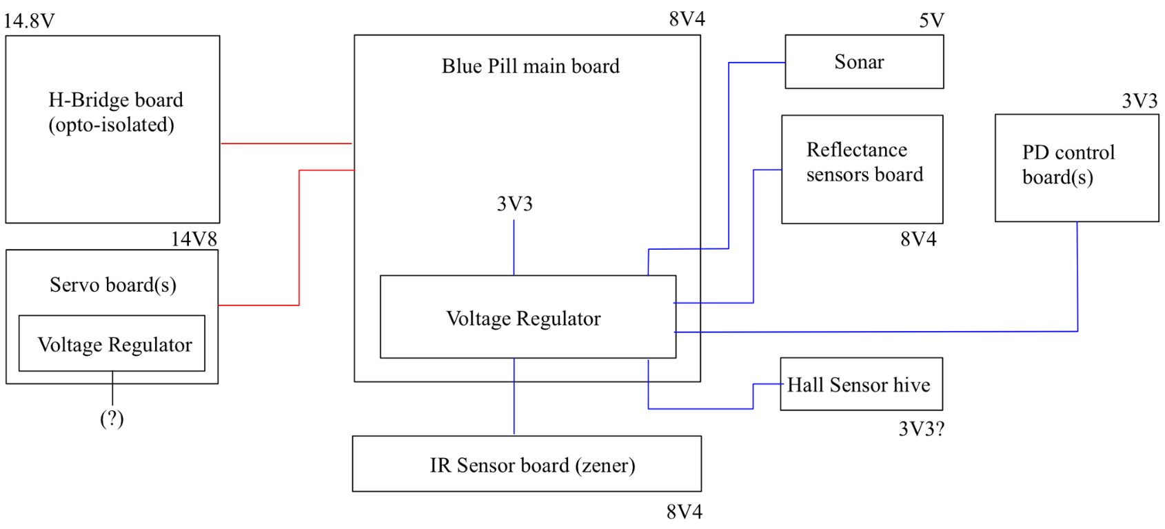
I chose to highlight shared grounds in blue here, and isolated/protected grounds in red. I’ll go over each part of the system in a second, but the big takeaways are:
- We chose to use one 8.4V and one 14.8V battery, this turned out to be a good choice as we ended up pretty tight for space and weight at the end.
- Big noise sources are isolated; this is because the microcontroller we’re using is quite sensitive to noise.
The microcontroller of choice for this course is the STM32F103C8T6/8 (commonly referred to as the Blue Pill board). With our mechanical design, I determined the following pinout:
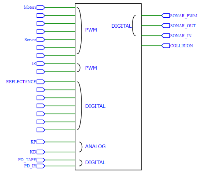
The required PWMs are mostly a result of our mechanical choices, we needed a minimum of two for the rear motors, another two for the motors in our pickup mechanism (didn’t change moving from servos to DC motors) and another one for the steering servo. I managed to save a some pins for the sonar with a clever little circuit I’ll share later, but let’s begin with the essentials:
The H-Bridge
The H-Bridge is a fundamental circuit used for switching the polarity of voltage across a load, commonly used to control the direction of inductor driven DC motors. The design we used was:

Note the opto-isolators on the Blue Pill outputs (labelled BP_OutX here). The component that really stands out here compared to what happens if you toss “H-Bridge circuit” into google is the LTC1161 IC; this is called a “gate driver” and is really just a combination of fast switching capacitor charge pumps that output a high voltage (as in, beyond the rails). This allows us to use exclusively NPN transistors to drive both sides of the H-Bridge (literature usually uses PNP transistors at the top, driven by a low voltage signal). But one wonders, why limit yourself to only NPN MOSFETs? The main reason is they’re simply easier to manufacture, and thus cheaper and more prominent in industry. For this use case, they’re also decently faster, which is important when you’re switching on and off rapidly (as a PWM does).
Implementing this circuit is usually pretty tricky. It’s quite involved, noisy and prone to issues, fortunately we didn’t have many issues with our initial proto-board implementation, other than it being pretty ugly and massive. The latter being a real issue, which is why I eventually designed and ordered some compact PCBs of this circuit (will add some pictures when I find the time).
Tape detection
This was the other fundamental circuit for our design idea. The circuit itself was quite simple:
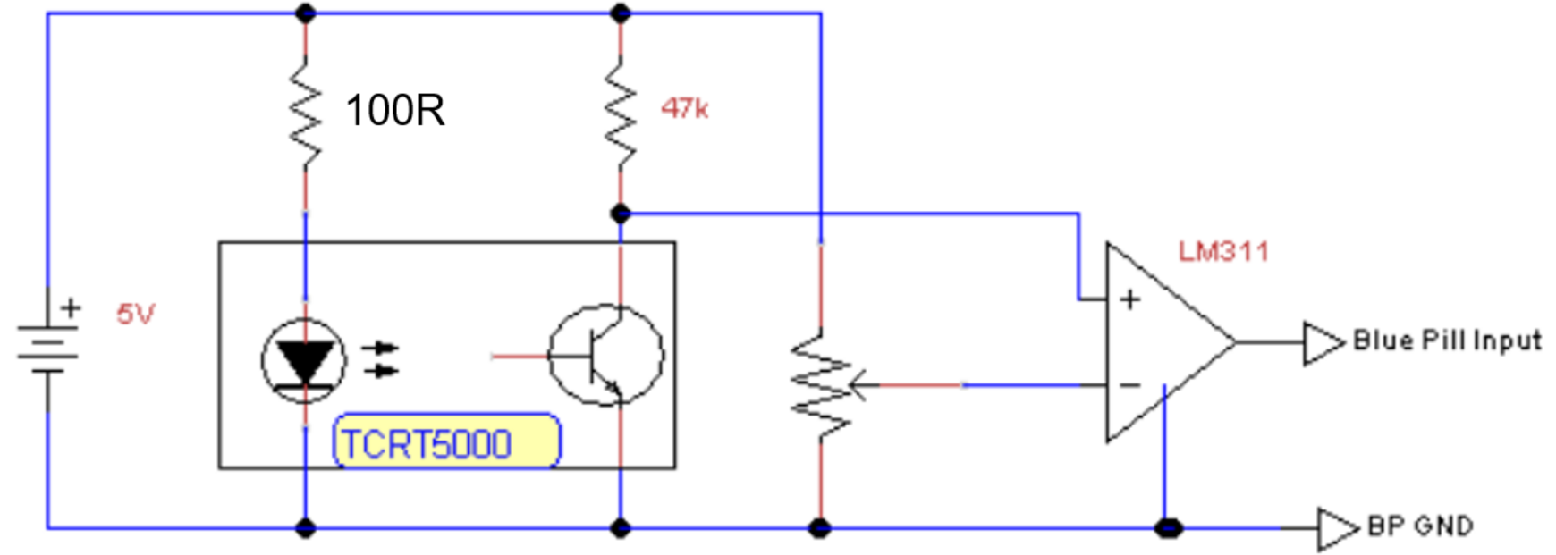
We used a digital input on the Blue Pill, with the potentiometer determining a threshold voltage for what is ‘black’ or ‘white’. Thus to tune the sensitivity of the sensors, we simply adjusted the potentiometer. Additionally, having the input be digital meant our robot (given appropriate tuning) would not be affected by the different colors on rainbow road.
We used six tape sensors because that gave us the most adaptability and reliability, and with our Ackermann steering allowed us to go really fast. This circuit turned out to be a recurring source of problems. First of all, the protoboard we used was quite big, messy and didn’t mount reliably on the steering mechanism; it popped loose quite often and the robot lost control. We also had some issues with resistor values, the initial choice was 47kΩ, but that made the sensors a bit too binary and under certain lighting conditions they simply would not detect black at all. Again, my approach to fixing this was simply design a neat and compact PCB for this circuit as well (also add this eventually):
Analog collision sensor
This is probably the most interesting circuit on the robot. The idea was quite simple: as robots were racing on the track simultaneously, collisions were likely to send a robot off track and thus force a restart, so naturally we’d want to avoid that. The initial idea was to simply use buttons on the bumper, but it would be even better if we could somehow brake before hitting another robot. Enter the HC-SR04 sensor (of which we had plenty):
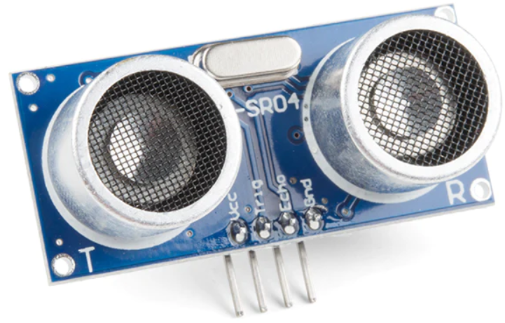
This would’ve worked fine in theory, but there was one flaw I noticed when learning how to interface this with the Blue Pill. The way the sonar works is it receives a high input for some specific duration (on the TRIG pin), which triggers the sonar output pin (ECHO) high and makes it send a sound wave. When it detects the reflection of the sound wave, the output pin goes low. The idea is to read for how long the ECHO pin stays high, and from the speed of sound calculate distance:
$$
\mathrm{distance} = \frac{1}{2} v_{\mathrm{sound}}\times \mathrm{time}
$$
The factor of $1/2$ accounts for the sound wave travelling back and forth. This is perfectly fine for many applications, but remember we wanted our robot to be really fast. If we opted for this method, we’d have to ping the sonar every loop of our PID program (or maybe every hundred loops if it’s quick) and then wait until the ECHO pin goes low again. This may not seem like a big deal, but remember we don’t even care about distance most of the time, only when there’s a robot arbitrarily close to our front. Ideally, we’d decide a comfortable distance to brake and then interrupt the loop when that distance is crossed. But this would require a binary high or low signal, which of course ECHO is not. This is where my circuit comes into play:
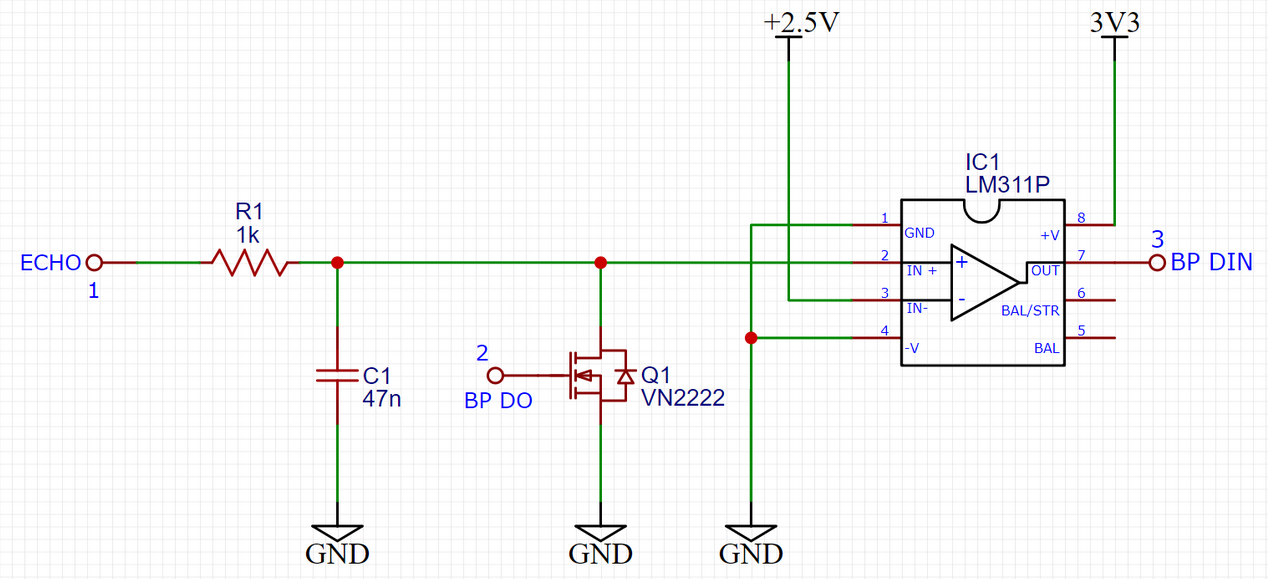
The logic is (in my humble opinion) beautifully simple. We constantly send a sound wave by driving the TRIG pin with a PWM, and we connect ECHO to the circuit. Depending on how long ECHO stays high for (i.e., the distance), the capacitor is charged to some voltage, governed by the time constant:
$$
\tau = RC
$$
This allows us to set an arbitrary voltage (distance) by deciding resistor and capacitor values. This voltage is then set to an LM311 comparator, and if it passes the threshold, the comparator reads high, and so does the Blue Pill. We can then just check this pin for an interrupt. On this interrupt we should of course discharge the capacitor, and we do so by connecting another Blue Pill pin to the MOSFET (and triggering it in our interrupt).
As nice as it sounds, there is a small issue on the circuit above. Can you spot it (while I try to find the final schematic)? Below is the circuit at work, the Blue Pill here is only supplying the PWM and interrupt pins, it doesn’t need to “think” while in the main loop:
The rest of this article isn’t finished yet so here’s a placeholder stylish lap: